Bankim Nagar, Siliguri, West Bengal
An auto coupling circuit links electrical or electronic sections so they can exchange power or signals in a controlled way. In a vehicle, that connection may involve a relay, sensor, control module, or trailer interface. The exact design depends on the system. A small wiring error can cause a warning light, an unreliable signal, or a component that fails to respond. Simple on paper; less simple under the dashboard.
For this introduction, automotive electronics engineer Alex Morgan is an illustrative expert voice, not a verified source. The line is original, not a recorded quotation: “A reliable Coupling Circuit Auto design makes the connection clear, protects each side, and stays predictable when conditions change.” That principle points to the key questions: What is being coupled? How does the circuit limit unwanted current or interference? What happens during startup, vibration, or a loose connection? A careful explanation should distinguish signal coupling from power switching, since the terms can be confused. It should also show real components and wiring paths, not just idealized symbols. One detail is easy to overlook: a circuit that works on a bench may behave differently in a hot, vibrating vehicle. That deserves a second look. This guide introduces the common circuit functions, components, and checks behind an auto coupling arrangement, while noting where vehicle-specific documentation matters.
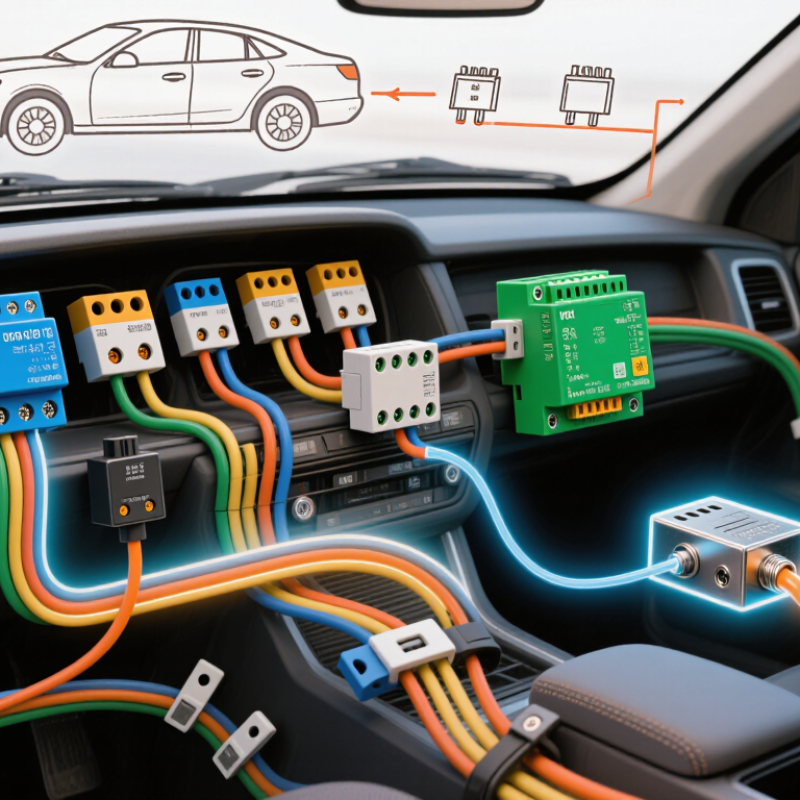
An auto coupling circuit is an electrical arrangement that connects two circuits automatically when specific conditions are met. The exact meaning can vary by equipment, but the basic idea is similar: a sensor or control signal detects a need, then a relay or contactor joins the electrical paths. For example, a voltage sensor might connect an auxiliary battery when the main supply reaches a set level. The circuit can disconnect it again when conditions change.
Its purpose is to manage power or signals without requiring someone to operate a switch each time. This can support continuity, reduce manual steps, and keep separate circuits isolated when coupling is unnecessary. A typical design includes a sensing element, a control section, switching contacts, and suitable overcurrent protection. These parts must be matched to the system’s voltage and current. A small detail matters: a contactor that works electrically may still be unsuitable for repeated switching or a warm enclosure. The terminology can also be confusing, so the equipment diagram should guide any interpretation.
Tips: Check the circuit diagram and switching ratings before testing. Use a meter to confirm when the contacts open and close. If the behavior seems inconsistent, inspect the sensor threshold and wiring connections.
What Is an Auto Coupling Circuit?
Main Components and Their Functions
An auto coupling circuit connects or disconnects electrical paths automatically when a set condition is met. Its exact design varies by application, so there is no single standard schematic. In a typical arrangement, a sensor or switch detects a change, such as a rising voltage or a closed position. A control unit or relay then sends a signal to the coupling device. That device may be a contactor or electronic switch, which joins the circuit and carries current to the connected load. Small parts matter, too. Resistors can limit current, while fuses help protect wiring during a fault. The power source and wiring complete the path. Keep their ratings in view.
A real inspection might reveal a loose terminal, warm insulation, or a relay that clicks without carrying power. These clues can narrow the search, but they do not prove the cause. Circuit diagrams and component specifications should guide testing. A neat diagram can still leave out useful details, so verify connections before replacing parts.
Tips: Disconnect power before handling exposed connections. Check terminal tightness and look for discoloration. Use a meter suited to the circuit’s voltage, and stop if readings seem inconsistent. Safety comes first.
An auto coupling circuit checks whether two electrical or mechanical parts are properly connected, then enables a path between them. The exact method depends on the equipment. A common design monitors a pilot contact, a change in voltage, or a small sensing current. When a plug seats, for example, a dedicated contact may close before the main power contacts engage. That small signal tells the control circuit that a connection is present. It is a modest detail, but the timing matters.
The signal usually passes through filtering and logic checks before a relay, transistor, or contactor is activated. These checks help reject brief spikes, loose-contact chatter, and incomplete insertion. Some circuits also confirm polarity or compare measured values against a safe range. Only when the readings meet the design’s conditions does the switching element complete the main circuit. In practice, this can take a fraction of a second. Not instantly.
Reliable detection needs more than a sensor. Engineers must consider worn contacts, dust, vibration, and changing electrical loads. A sensor can report “connected” while the physical fit remains poor, so a single reading may not tell the whole story. Testing across repeated connections helps reveal that gap. The circuit should also return to a safe state if the signal disappears or becomes inconsistent. That behavior is easy to overlook. A clear wiring diagram and documented test limits make troubleshooting more dependable.
An auto coupling circuit connects or disconnects electrical paths when a set condition is met. The term is not perfectly standardized, so check the circuit diagram and intended use. Common designs include relay-based circuits, which use a coil to switch contacts, and solid-state circuits, which use transistors or MOSFETs. Relays handle straightforward switching and are easy to inspect. Solid-state types can switch quickly and quietly, but may need heat management.
In vehicles, these circuits can manage auxiliary battery charging, trailer-light connections, or automatic loads such as cooling fans. A relay-based charging circuit may connect a secondary battery only when the engine is running. A solid-state switch can control a fan when a temperature sensor reaches its threshold. Small details matter: wire size, fuse placement, current rating, and grounding all affect safe operation. A circuit that works on a bench may behave differently amid vibration, heat, and moisture.
Tips: Match the switch rating to the actual load, including its startup surge. Install protection close to the power source. Test with a meter before connecting sensitive electronics. Keep it simple. If the wiring diagram is unclear, pause and verify each connection; guessing is a poor repair method.
| Circuit Type | How the Coupling Works | Typical Characteristics | Common Applications | Important Design Consideration |
|---|---|---|---|---|
| Autotransformer Coupling | A single winding with one or more taps transfers energy between circuit sections. Part of the winding is shared by the input and output. | Can step AC voltage up or down; often smaller and more efficient than an equivalent two-winding transformer. It does not provide galvanic isolation. | AC voltage adjustment, motor starting, and interconnection of AC systems with different voltage levels. | Because the windings are electrically connected, insulation, grounding, fault protection, and voltage ratings must be considered carefully. |
| Two-Winding Transformer Coupling | Energy transfers through magnetic flux between separate primary and secondary windings. | Can provide galvanic isolation and change voltage or impedance; performance depends on frequency, core, and winding design. | Power supplies, audio equipment, signal isolation, and impedance matching. | Select a transformer rated for the expected voltage, current, frequency, insulation level, and load. |
| Capacitive (RC) Coupling | A capacitor passes changing signals between stages while blocking steady DC; resistors commonly set the operating bias and load. | Simple and widely used for AC signals. The low-frequency response depends on the coupling capacitor and the resistance seen by it. | Audio amplifiers and cascaded transistor or operational-amplifier stages where DC levels should remain separate. | Choose the capacitance and voltage rating to suit the signal frequency, circuit impedance, and maximum DC voltage. |
| Inductive Coupling | A changing current in one coil creates a changing magnetic field that induces a signal in a nearby coil. | Transfers AC or changing signals without a direct electrical connection; coupling strength depends on coil geometry, spacing, and frequency. | Inductive sensors, resonant circuits, and short-range wireless power transfer. | Nearby metal, coil alignment, and electromagnetic interference can affect performance. |
| Direct (DC) Coupling | Circuit stages connect directly, allowing both changing signals and DC levels to pass between them. | Supports signals down to DC, but the bias and offset of one stage can affect the next. | Instrumentation amplifiers, sensor interfaces, and circuits that must process very low-frequency or DC signals. | Check bias compatibility, offset accumulation, and input/output voltage limits across all stages. |
What Is an Auto Coupling Circuit?
Safety Features and Common Faults
An auto coupling circuit controls how two electrical sections connect and disconnect. Depending on the equipment, it may use sensors, relays, and a control unit to confirm that coupling is safe. Interlocks can prevent connection when alignment is poor or a cover is open. Some systems also monitor current or temperature. These safeguards reduce risk, but they do not replace inspection.
Common faults include worn contacts, loose wiring, failed sensors, and relay chatter. A technician might notice intermittent operation, a warning light, unusual heat, or a clicking sound near the control panel. Moisture and vibration can also cause problems over time. Don’t assume a reset has fixed the cause. That can hide a fault until the next operation.
Tips: Check for visible damage and record when the fault occurs. Is it worse after rain, vibration, or repeated use? Keep hands away from live components. Isolate the equipment according to its service procedure, then have a qualified technician test the circuit. A symptom can be misleading; I’ve seen a loose connection look like a sensor failure. Verify before replacing parts.
An auto coupling circuit uses electrical controls to engage or disengage a coupling mechanism. Depending on the system, safety measures may include a fuse, relay, and interlock that prevents operation under unsafe conditions.
Illustrative waveform: The trace shows a generic 12 V control signal switching on and off; it is not a vehicle-specific specification. Common faults include a blown fuse, loose or corroded connections, damaged wiring, a failed relay, or a faulty interlock. Always check the system’s service information and isolate power before inspection.
Hi! Simply click below and type your query.
Our experts will reply you very soon.
